If you’re a homeowner and planning to engage engineers and technicians to perform soil testing and site classification on your block of land, it’s important to understand what’s involved in the process and how to read your report. In part, thish is because you are responsible for ensuring your soil conditions remain stable over the life of your building.
We’ve covered key issues to be aware of when designing your structure and maintaining your property.
In April 2003 the Queensland Building Services Board instigated a review of the causes of footing and slab movement. The review focused on the design and construction of footings and slabs including legislation and standards as well as skill levels and education of practitioners. It also considered the escalating costs to BSA’s statutory fund.
Preliminary findings of a research project commenced in May 2003 identified two areas that required special attention. They were: Engineering Investigation and Design and Construction Practices.
After informing industry of the review in September 2003, the Queensland Building Services Board recently endorsed a new Policy for Rectification of Building Work in residential construction. This includes work that causes footing slab movement.
A Fact Book, distributed throughout Queensland, is aimed at ensuring that all participants in the building industry are properly informed about, and understand how to comply with, the no fault provisions of the new policy. Similarly, a further BSA education initiative will endeavour to ensure homeowners are made more aware of their responsibilities for the ongoing maintenance of their homes.
Please read your requirements and make use of the resources from BSA’s website, ensure you fully comprehend the requirements of the relevant sections of the Building Code of Australia and have an understanding of Australian Standard 2870.
Your understanding and compliance with these requirements and your assistance in ensuring you as homeowners are aware of your own maintenance responsibilities will help minimise the incidence of footing and slab movement. This, in turn, will reduce your costs for rectification, and ultimately, the burden that industry bears due to problems created by defective work.
Previous policy
To avoid responsibility for rectification of subsidence under the previous policy, the contractor only had to rely on information provided by an engineer, follow the requirements of the engineer as specified and have the work certified by a competent person.
This is NOT the case now.
Current policy
Where contracts or preliminary agreements are entered into after 1 September 2004, the contractor and owner must also ensure that the engineer is provided with all the information relevant to the construction. The contractor must also ensure that the engineer provides a design and certifies that it complies with the information the contractor has provided and the requirements of the relevant codes and standards.
Both the performance of footing and slab systems and the continued serviceability of buildings rely on the contractor and the homeowner complying with construction practices and site maintenance conditions. The Australian Standard relies on normal conditions being maintained throughout the life of buildings.
Both the contractor and the homeowner have a duty to know their individual responsibilities.
Methods adopted are in accordance with guidelines specified in AS 2870 – 2011, appendix D. Potential surface movement and the resultant site classification are therefore consideration of the local depth of the zone of consideration of significant soil moisture variations and the entire ground profile. This includes the influence of “reactive” clay based soils and/or the presence of fill, as well as the effect of “stable” materials such as dense sands or shallow rock. Site classification is divided into various classes, dependent upon the “Ys” (potential movement). Classifications are:
| Site Classification Symbols | Description |
| A | Most shallow rock sites and some sand sites with little potential for movement through moisture change. |
| S | Slightly reactive sites; have only slight potential for ground movement through moisture change. |
| M | Moderately reactive sites; can undergo moderate ground movement through moisture change, May be considered as your average site. |
| H1 & H2 | Highly reactive sites; can experience a high level of ground movement. Additional costs are generally incurred in building on such sites. |
| E | Extremely reactive sites; can experience extremely high amounts of ground movement. Special considerations should be taken into account when building on these sites |
| P | Problem sites which generally have soils associated with uncontrolled fill, mine subsidence, landslip, or soft or collapsing soils. |
*Additional costs can be incurred on sites due to possible difficulties in excavations/earthworks.
Site testing is constructed in strict accordance with AS 1726 – 1993, “Geotechnical site investigations”.
Insitu scala-cone penetrometer and shear vane testing are converted to allowable bearing pressures. Refer respectively to “Determination of Allowable Bearing Pressures Under Small Structures” (1977) by MJ Stockwell and “Skemptons’s Theorem” (1954).
Clay-based soils are sampled and tested for their plasticity parameters, in accordance with AS 1289 3.1.2, 3.4.1 and 6.3.2.
STA Consulting Group Pty Ltd trading as STA Consulting Engineers is also NATA (National Association Testing Authorities) accredited for appropriate test procedures.
The performance of the footings and/or slab is largely dependant upon a responsible approach by the builder and the owner/occupant towards vegetation and site drainage. It is not recommended to have trees within a distance from the residence equivalent to:
75% of the mature tree height, for class “M” sites 100% of the mature tree height, for class “H” sites 150% of the mature tree height, for class “E” sites
Alternatively, root barriers MUST be adopted if the removal of some trees is not possible. A root barrier is usually installed between the foundations and adjacent trees within their mature height from the foundation and where there is expansive clay soil to prevent tree roots from consuming moisture from the soil under the area of concern.
Root barriers can be made of any impermeable durable material that can withstand burial in soil for an extended period of time. The depth required for the root barrier is greatly dependant on the tree species, as the root systems on different tree types will vary in depth at which they are embedded. It is recommended that a qualified horticulturist be consulted prior to the installation of a root barrier if there is concern for the health of the tree whose roots are to be cut.
Removal of large trees may cause an adverse effect, as soil moisture is gradually restored, and this may cause clays to swell and may lift shallow footings. Water MUST never be permitted to pond around foundations.
Additional Critical Issues are:
The previously mentioned restrictions may seem onerous for new homeowners, however, the lack of site maintenance on a reactive clay site can cause damage to the house. The damage to houses caused by reactive clays is mostly unsightly cracks in the brickwork. In the typical Australian brick veneer house, the brickwork does not support the structure. It is the timber frame that carries the walls and roof loads, so brick cracks do not affect the structural safety of the house.
Unless STA Consulting Group Pty Ltd trading as STA Consulting Engineers has been instructed about existing or proposed mining projects or slope instability, any of which can adversely influence ground conditions then the findings and recommendations contained in this report are not relevant and can not be relied upon.
Trees and large shrubs require amounts of water to survive. Tree roots absorb moisture from in the soil, and as soils dry around the root systems they will naturally extend and grow in the direction of soil moisture. This drying out of soil can cause considerable movement of the ground level, especially when combined with highly reactive (clay) soils can result in uneven settlement of foundations.
This uneven settlement may cause substantial damage to the foundations of building and walls as well as driveways & pathways.
| Alt text: Graphic showing typical drainage from shrinkage settlement impacting the footing and wall. Local corner settlement | Alt text: Graphic showing cracked wall due to uneven footing settlement from tree roots. Wall Cracking |
| Alt text: Graphic showing cut off wall being used to protect footings. Cut-off wall | Alt text: Graphic showing underpin used to reinforce footings.Underpinning |
After damage has occurred, the underpinning of footings and more costly repairs (even the most drastic, demolition) is often the only option.
Installation of Root Barriers will protect house foundations as well as pipes, walls and paths and will eliminate the problem of uneven settlement of foundations. With the installation of a Root Barrier, trees which in the past had to be removed because of their damaging effects can remain and exist quite happily alongside buildings without causing any problems underground.
It is not recommended to have trees within a distance from the residence equivalent to;
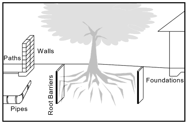
Alt text: Graphic showing root barriers installed to protect foundations, pipes, and walls from tree roots.
Where trees are located within the recommended distances outlined above, the construction of a vertical cut-off wall will be required to effectively prevent tree roots from gaining access to structures, therefore stabilising the soil by greatly reducing moisture movement. The vertical cut off wall should be constructed a minimum of 1 metre from the footings of the structure and generally 1 metre in-depth, however this may depend on soil types.
Batter angles must comply with local government requirements and are to conform as follows:
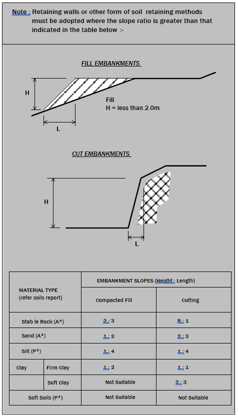
Alt text: Diagrams and table showing data on suitable batter angles for embankments.
For totally filling the pad to level, CBR 15 or decomposed rock is recommended. Fill placed behind a brick cavity is to be of a granular base consisting of either sand, CBR 15, decomposed rock or “crusher– dust”. Highly reactive clay based soil is not recommended for use as fill.
Fill is to be placed in 150 mm deep layers, moistened and compacted to achieve the equivalent of 95% standard compaction.
Compaction testing is to be in accordance with AS 1289, section 5.2.1. A vibrating “sheeps-foot” roller is recommended for compaction of the totally filled pad. A “vibrating-plate” or a “wacker-packer” is recommended for compaction of fill restrained by a brick-cavity.
Note: fill is not to be compacted within 500 mm of the brick cavity base (retaining wall).
When it is proposed to adopt the use of floor tiles it is recommended that:
If previous structures such as tennis courts and slabs for large sheds/other buildings are removed to allow construction of the dwelling, then uneven ground movements may result since possible ground movements due to moisture changes may have already occurred under the removed slab. Such conditions should be identified at the time of the site inspection and allowed for in the design.
The ground around this type of feature will normally be quite wet and any ground movement due to moisture would probably have already occurred. Again, if building over these areas, differential ground movements and the possible loss of bearing capacity should be allowed for in the design and detailing of the building.
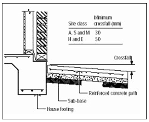
Alt text: Diagram showing crossfall based on site class.
Paths, driveways, and other paving all act as impermeable membranes in terms of soil moisture and, similar to the house slab, will cause ground movements due to moisture changes in the soil. Paving provides an excellent ‘buffer zone’ around the house that assists in reducing moisture variations around the footings. However, to work effectively, it is essential that paving has sufficient crossfall away from the house for the expected reactivity or ground movement of the site
If laying pavements in summer, care should be taken to ensure that crossfalls are adequate to accommodate soil swelling in winter. All surface water should be drained to the stormwater system. Variations in paving between one side of the house and the other should be minimised, as this may cause differential movement of the footings. Further, if it is not possible to construct any planned paving immediately, then plastic sheeting with gravel spread on the top, graded away from the house, provides a practical temporary measure to facilitate the reaching of stable moisture condition.
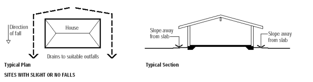
Alt text: Diagrams showing drainage considerations and impacts on soil and footings.
How will any earthworks affect natural site drainage? What measures will need to be taken to keep water away from footings?
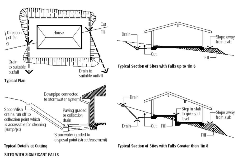
To minimise variations in moisture content in the foundation, especially under the footing, an effective drainage system must be installed and maintained for the site and building. This involves directing both surface and subsurface water away from the house. This is particularly pertinent when cuts are involved with slabs supported on ground. The minimum requirement will be that the ground is sloped away from the slab with a dish drain at the base of the batter or retaining wall to take surface water away from the high side of the house. On clay sites, sealed surface drains should be used since subsoil drains may introduce moisture into the foundation. Dish drains on the high side of unprotected batters may also be required if the face is likely to be eroded by run-off.
Stormwater is the greatest source of surface runoff and large quantities are collected by the roof of a house. To ensure effective drainage, all downpipes need to be connected to an adequate stormwater system and directed away from the house, generally to the street or other stormwater drain.
(Note: Some authorities prefer drainage to be retained on site where possible or held for a time before discharging into stormwater.)
Similarly, paved areas should be graded to collection points that are connected to the stormwater system and are accessible for cleaning.
Individual sites, especially cut-and-fill sites, will have specific drainage requirements which should be detailed on a site or drainage plan prepared by the engineer or builder. On cut-and-fill sites, all batters and drainage should ensure adequate site drainage, spoon/dish drains and/or agricultural drains will generally be required to prevent surface and subsurface water draining towards the house. Agricultural drains are also used in low-lying areas or on sites that have a tendency to collect excessive water.
The maintenance of the site around a new home is an important factor in the long-term performance of the footing system. The primary objective of this maintenance is to minimise the variation in soil moisture levels around the footings that could lead to excessive soil movement and possible distress of the superstructure and/or footing. When the slab forms part of the termite barrier system for the house, then it is also necessary to maintain the effectiveness of that barrier with appropriate maintenance activities.
When a concrete slab-on-ground is used as part of the termite barrier system as outlined in AS 3660.1, then it cannot be too highly stressed that regular inspections and maintenance of the slab and surroundings by a competent professional is required to ensure that any termite infestation is detected and treated promptly.
Ongoing maintenance and inspections on a regular basis is a requirement of AS 3660.1 and owners should be clearly advised of their responsibilities to ensure that their investment is properly protected.
Leaking taps, downpipes, sewers, gutters and drains can also affect the moisture content of the soil and these must be inspected regularly to insure against damage to the footings. Similarly, gutters, downpipes and collection points can get blocked with leaves and other debris, preventing the effective drainage of stormwater away from the house. Again, regular inspections and maintenance should be carried out to prevent blockages.
It is important for the builder to make the homeowner aware of the maintenance issues associated with ensuring the long- term performance of the footing system.
As the supply of level building sites diminishes, the need to level or terrace to create level building platforms for house construction will increase. Also, on many developed sites there is often a need to level the front and/or back yards to fully utilise the space for carports, gardens, play and entertainment areas.
Cut-and-fill is a common method of achieving level areas but if a batter is used between the level areas so created, a maximum area of level round will not be achieved. Furthermore, on some sites, suitable fill may have to be imported and on others spoil disposed of, both of which will add to the cost. The alternative is to use retaining walls.
Apart from retaining the soil, retaining walls can also help protect against erosion on susceptible sites. The requirements of a functional retaining wall include structural stability, durability against the exposed environment, and provision or drainage. Appearance will also usually be important.
Concrete retaining walls provide a durable solution that is required of a structure in contact with soil and exposed to constant wetting and drying. Concrete does not rot and will not be eaten away by termites. The wide range of available options ensures that a suitable solution can be found for any situation.
The first step in any retaining-wall project is to check with the local authority to see if planning approval is required. This varies between authorities and is usually related to wall height and drainage provisions.
Authorities may require drawings showing a site plan and structural details accompanied by a consultant’s design certification. Except for minor low-rise garden walls, up to, say, 600mm high, engineering advice should be sought on the wall design for the given site.
Drainage is an important aspect of any retaining-wall project. Water must not be allowed to build up behind the wall. Retaining walls are designed to resist earth pressures exerted by only the weight of soil retained. These are much less than the hydrostatic pressure exerted by water dammed behind the wall.
The following parameters influence the design of the retaining wall:
Apart from retaining the soil, retaining walls can also help protect against erosion and susceptible sites.
Soil restrained by a vertical or near-vertical retaining wall exerts a lateral pressure against the wall. This pressure tends to cause sliding and /or rotation of the wall which must, therefore, be designed to resist these forces over the intended design life. Apart from structural design, durability and drainage must also be given particular attention. The design should be undertaken by a professionally qualified consultant to suit the particular building site parameters.
Now let’s talk about retaining wall types and systems.
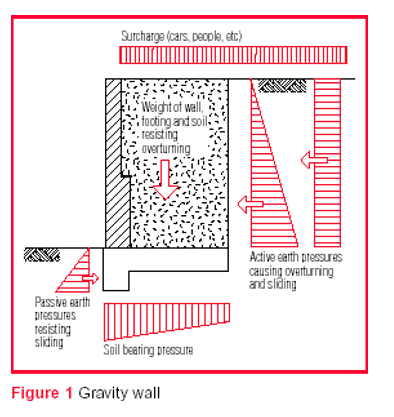
Alt text: Diagram showing gravity wall.
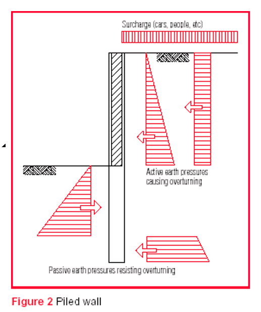
Alt text: Diagram showing piled wall.
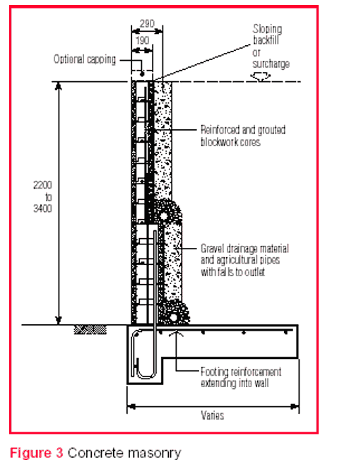
Alt text: Diagram showing concrete masonry retaining wall.
Retaining walls can be grouped into two distinct categories by considering the way in which they resist the lateral force exerted by the soil:
Within these two categories, there are a number of different and innovative concrete retaining wall types available. Some manufacturers offer technical support, in the form of brochures showing engineer-designed details, for their particular wall type.
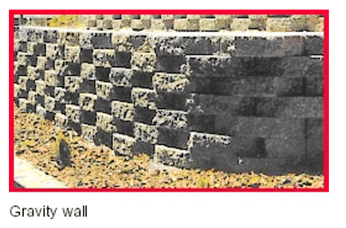
Alt text: Photo of a gravity wall.
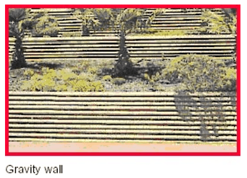
Alt text: Photo of a gravity wall.
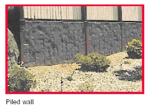
Alt text: Photo of a piled wall.
Reinforced concrete masonry walls
Reinforced concrete core-filled hollow concrete blocks are laid on a reinforced concrete footing to form a cantilever gravity retaining wall. This is an extremely popular system offering benefits that include zero lot lines, a vertical wall face and a range of possible finishes. They are economical to around 3 m in height. Full details of block wall construction is provided in Masonry Wall
4 design for Earth Loads – Retaining Walls published by the Concrete Masonry Association of Australia.
Insitu concrete walls
Cantilever gravity walls can be constructed entirely from reinforced concrete. They are similar to reinforced masonry walls. The wall is cast on-site and the exposed vertical face can be treated in many ways, including the use of textured form liners to give particular patterns or motifs.
Dry stacked segmental block walls
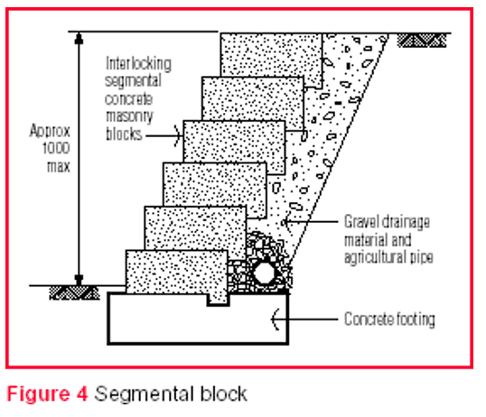
Alt text: Diagram showing a segmental block.
Low-height retaining walls (generally 1 m and less) can be constructed from dry stacking specially-manufactured segmental concrete masonry blocks. The blocks interlock, which provides a positive connection between blocks. These walls behave as a gravity wall and are available in a variety of colour and face finishes. They are extremely popular for DIY installations as they are easy to erect. Local concrete masonry suppliers should be contacted for specific system details.
Segmental block with soil reinforcement walls
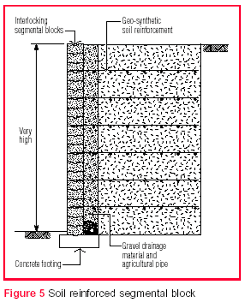
Alt text: Diagram showing a soil reinforced segmental block.
Walls of similar appearance to dry-stacked segmental concrete masonry block walls but without the height limitation can be constructed by dry stacking similar segmental concrete masonry blocks connected to layers of horizontal geo-synthetic soil reinforcement placed in the backfill behind the wall units. The blocks have an interlocking shape, which provides a positive connection between the blocks and the soil reinforcement. These walls are a gravity system. However, unlike the earlier segmental block walls, they utilise the soil mass behind the wall to help resist the lateral soil forces. This is usually referred to as ‘reinforced soil technology’. It is an engineering solution and requires supervision by a competent contractor.
Local concrete masonry suppliers should be contacted for specific system details.
Crib walls
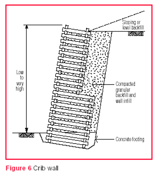
Alt text: Diagram showing a crib wall.
Crib walls are constructed from precast concrete components that interlock and form an open crib. The spaces between the units are filled with gravel making the system free draining. Crib walls can be economically designed and built for a wide range of wall heights. Wall aesthetics can be enhanced by planting vines on top to the wall and in the spaces above the cribs to drape down over and soften the appearance of the wall face.
*Concrete offers a wide range of retaining wall options to suit a particular project’s requirements. For the various manufactured systems check with the suppliers for details and advice.
Concrete sleeper
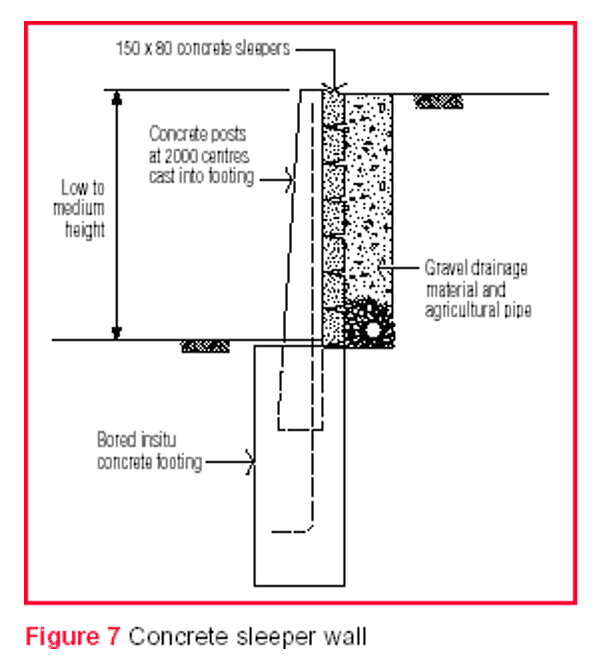
Alt text: Concrete sleeper wall diagram.
Precast concrete sleeper planks span horizontally between vertical precast concrete posts that are embedded into the ground. Usually, the posts are cast into a bored insitu concrete footing. This is a piled system that relies on the embedment and strength of the post and sleeper units to resist lateral soil forces. It is a low-cost system and can achieve ‘zero-lot-line construction’. Posts and sleepers can be coloured and face textured to resemble timber grain, slate, etc.
Overall, concrete offers a wide range of retaining wall options to suit a particular project’s requirements. For the various manufactured systems check with the suppliers for details and advice. Remember that for all walls, foundation preparation, drainage and good workmanship are essential. Engineering advice should always be sought and council requirements ascertained prior to retaining wall construction.
That’s it for our homeowners’ reference guide. Well done if you got through it all (although we understand if you just skipped ahead to the bits you needed to know!).
Remember, if you need to download the pdf, you can grab it here.
If you have any questions about documentation, terms, soil testing, or any of the other services we offer here at STA, please don’t hesitate to contact us. We’ll be happy to help.
