Are you a builder or homeowner and planning to engage a consultant to do soil testing and site classification? We’ve put together this guide to help you understand key terms and procedures that make up part of the soil testing process.
Methods adopted are in accordance with guidelines specified in AS 2870 – 2011, appendix D. Potential surface movement and the resultant site classification are therefore consideration of the local depth of the zone of consideration of significant soil moisture variations and the entire ground profile. This includes the influence of “reactive” clay-based soils and/or the presence of fill, as well as the effect of “stable” materials such as dense sands or shallow rock.
Site classification is divided into various classes, dependent upon the “Ys” (potential movement). Classifications are:
| Site Classification Symbols | Description |
| A | Most shallow rock sites and some sand sites with little potential for movement through moisture change. |
| S | Slightly reactive sites; have only slight potential for ground movement through moisture change. |
| M | Moderately reactive sites; can undergo moderate ground movement through moisture change, May be considered as your average site. |
| H1 & H2 | Highly reactive sites; can experience a high level of ground movement. Additional costs are generally incurred in building on such sites. |
| E | Extremely reactive sites; can experience extremely high amounts of ground movement. Special considerations should be taken into account when building on these sites |
| P | Problem sites which generally have soils associated with uncontrolled fill, mine subsidence, landslip, or soft or collapsing soils. |
*Additional costs can be incurred on sites due to possible difficulties in excavations/earthworks.
Site testing is carried out in strict accordance with AS 1726 – 2017, “Geotechnical site investigations”. In situ scala-cone penetrometer and shear vane testing are converted to allowable bearing pressures.
Refer respectively to “Determination of Allowable Bearing Pressures under Small Structures” (1977) by MJ Stockwell and “Skempton’s Theory” (1954).
Clay-based soils are sampled and tested for their plasticity parameters, in accordance with AS 1289 3.1.2-2009(R2017), AS 1289.3.4.1-2008(R2016) and AS1289.6.3.2-1997(R2013).
STA Consulting Group Pty Ltd trading as STA Consulting Engineers is also NATA (National Association Testing Authorities) accredited for appropriate test procedures.
Since the advent of Australian Standards AS 2870 in all its iterations, it has been a requirement to quote a Y’s value in the determination of “Site Classification”.
Y’s & Y’t Calculations
STA Consulting Engineers when undertaking the determination of a site classification uses methodologies as per AS2870-2011 “Residential Slabs and Footings”. These site classifications are used in the determination of foundation designs and construction for a single dwelling house, townhouse or similar structure which may be detached or separated by a party wall or common wall, including buildings classified as Class 1 and Class 10a in accordance with the National Construction Code (Building Code of Australia).
Site classification is based on the expected ground surface movement and the depth to which this movement extends. Classification of sites where ground movement is predominantly due to soil reactivity under normal moisture conditions shall be classified based on the expected level of ground movement as nominated in AS2870-2011 Section 2 Site Classification Table 2.1 and section 2.1.3 “Classification of other sites”.
STA Consulting Engineers underlines and summarises the importance of site classification approach in order to determine the most adverse condition for the proposed foundation whether be it a future slab on ground or post/pole type construction. STA Consulting Engineers undertakes the calculations to be holistic, where the site is characterised by many values of Y’s determined for every borehole and taking into consideration the future earthworks from the site (existing RL level and future RL level).
The Y’t is considered based on type of tree and the minimum distance from tree to the house. In that instance, the Y’t will affect only the boreholes found in the zone of influence of the tree, not all of them. Also, the settlements effect is considered if there is information related to the level of fill and the age of the fill. The settlements can influence the Y’s in two different ways depending on hogging or sagging mode.
To minimise the risk of over-designing or under designing process, the map with characteristic values for suction zones is interconnected with our Y’m spreadsheet calculator.
Our results relate to the slab movements and required stiffness are close to a real site situation with our values being a more comprehensive guide to the foundation designer to ensure a more considered, cost effective and doubtless design.
STA Consulting Engineers under takes the site classification and there after the foundation design in accordance with:
*STA Consulting Group Pty Ltd trading as STA Consulting Engineers calculates the Ys using both shrink/swell and Atterberg test method. In the foundations design criteria, the worst of the two results are used in the calculation of potential foundation movement.
The performance of the footings and/or slab is largely dependent upon a responsible approach by the builder and the owner/occupant towards vegetation and site drainage. Existing trees are accounted for within the foundation design taking into account their mature size and height.
Where tree are to be planted after the commissioning of the foundation design report, a root barriers MUST be adopted. A root barrier is usually installed between the foundations and adjacent trees within their mature height from the foundation and where there is expansive clay soil to prevent tree roots from consuming moisture from the soil under the area of concern.
Root barriers can be made of any impermeable durable material that can withstand burial in soil for an extended period.
The depth required for the root barrier is greatly dependant on the tree species, as the root systems on different tree types will vary in depth at which they are embedded. It is recommended that a qualified horticulturist be consulted prior to the installation of a root barrier if there is concern for the health of the tree whose roots are to be cut.
Removal of large trees may cause an adverse effect, as soil moisture is gradually restored; this may cause clays to swell and may lift shallow footings. Water MUST never be permitted to pond around foundations.
Additional Critical Issues are:
The previously mentioned restrictions may seem onerous for new homeowners; however, the lack of site maintenance on a reactive clay site can cause damage to the house. The damage to houses caused by reactive clays is mostly reflected in unsightly cracks in the brickwork. In the typical Australian brick veneer house, the brickwork does not support the structure. It is the timber/steel frame that carries the walls and roof loads, so brick veneer cracks do not affect the structural safety of the house.
Unless STA Consulting Group Pty Ltd trading as STA Consulting Engineers has been instructed to the contrary, findings and recommendations contained in this report are not relevant should existing or proposed mining projects and/ or slope instability adversely influence the ground conditions.
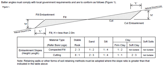
Alt text: Diagram and table showing angles for embankments
For totally filling the pad to level, CBR 15 or decomposed rock is recommended. Fill placed behind a brick cavity is to be of a granular base consisting of either sand, CBR 15, decomposed rock or “crusher – dust”. Highly reactive clay-based soil is not recommended for use as fill.
Fill is to be placed in 150 mm deep layers, moistened and compacted to achieve the equivalent of 95% standard compaction. Compaction testing is to be in accordance with AS 1289-2003, section 5.2.1. A vibrating “sheep’s-foot” roller is recommended for compaction of the totally filled pad. A “vibrating-plate” or a “wacker-packer” is recommended for compaction of fill restrained by a brick-cavity.
Note: Fill is not to be compacted within 500 mm of the brick cavity base (retaining wall).
Existing or proposed services may have an impact on the design recommendations supplied by the designing engineer. Therefore, it is strongly recommended that you contact the local authority and confirm the positioning of any underground services that may be on-site prior to any proposed excavations.
Excavations, retaining walls, swimming pools and other structures which are built near the proposed building after its completion may change the soil conditions and STA Consulting Group Pty Ltd trading as STA Consulting Engineers or another engineer must be consulted prior to any such work being undertaken. Should soil conditions vary significantly from those indicated in this report, or if the proposed building design or proposed site preparation details are changed, STA Consulting Group Pty Ltd trading as STA Consulting Engineers is to be contacted immediately in order to present amended recommendations.
Trees and large shrubs require various amounts of water to survive. Tree roots absorb moisture from in the soil, and as soils dry around the root systems they will naturally extend and grow in the direction of soil moisture.
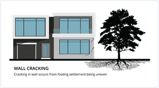
Alt text: Graphic showing wall cracking a result of uneven footing settlement due to a tree.
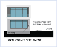
Alt text: Graphic showing local corner settlement due to shrinkage settlement.
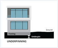
Alt text: Graphic showing underpinning repair to footings.
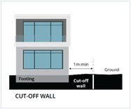
Alt text: Graphic showing cut off wall 1m+ from footings to protect them.
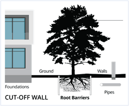
Alt text: Graphic showing cut off wall solution to protect foundation from root barriers and other issues.
This drying out of soil can cause considerable movement of the ground level, especially when combined with highly reactive (clay) soils, can result in uneven settlement of foundations. This uneven settlement may cause substantial damage to the foundations of buildings and walls as well as driveways and pathways.
After damage has occurred, the underpinning of footings and more costly repairs (even the most drastic, demolition) is often the only option.
Installation of Root Barriers will protect house foundations as well as pipes, walls and paths and will eliminate the problem of uneven settlement of foundations. With the installation of a Root Barrier, trees which in the past had to be removed because of their damaging effects can remain and exist quite happily alongside of buildings without causing any problems underground.
Change the following statement to comply with Appendix CH4 or CH5
It is not recommended to have trees within a distance from the residence equivalent to:
Where trees are located within the recommended distances outlined above, the construction of a vertical cut-off wall will be required to effectively prevent tree roots from gaining access to structures, therefore stabilising the soil by greatly reducing moisture movement. The vertical cut off wall should be constructed a minimum of 1 metre from the footings of the structure and generally 1 metre in depth, however this may depend on soil types.
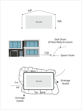
Alt text: Graphic showing potential site drainage.
Site preparation must include provision for a ground fall of no less than 1 in 20 away from the house for a distance of at least 1 metre and where possible, a spoon drain at the base of cut banks directing surface drainage around and away from the footings. Refer to figure 1.
When it is proposed to adopt the use of floor tiles it is recommended that:
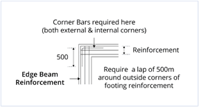
Alt text: Diagram showing edge beam reinforcement.
Steel wire reinforcing fabric and bars are to conform with AS/NZS 4671-2001 which supersedes AS 1304, (“Hard Drawn Steel Wire Reinforcing Fabric for Concrete”) and AS 1302 (“Steel Reinforcing Bars for Concrete”).
Lap Lengths
NOTE: At extensions under eaves/bay windows continuation of footings beams are generally required.
Reinforcement Alternatives
Numerous (not all) alternatives for footing and slab reinforcement are indicated on the footing/slab design detail. Should a preferred reinforcement not be specified, you must contact STA Consulting Group Pty Ltd trading as STA Consulting Engineers for confirmation as to its acceptability.
Masonry like brick or aerated concrete is brittle and weak in tension. Therefore, it is affected by distortions causing tension or tensile stresses. There are two essential causes of distortion which can cause tensile stresses.
Movements Within Masonry
These movements are caused by:
Usually in small buildings thermal movements in masonry are of little consequence. However, the expansion/shrinkage characteristics may be of importance.
If suitable precautions are not taken, the result of distortions within masonry may take place. Sometimes in small buildings it may be unnecessary to take any particular precautions, and at other times it may be essential if cracking is to be avoided.
Expansion of Clay Bricks
All clay bricks expand over a long period after leaving the kiln. This may continue for many years. The amount of expansion varies considerably between varieties of brick being affected by the raw materials used in manufacturing the bricks and the burning in the kiln.
Shrinkage of Concrete Masonry
Concrete blocks and bricks shrink. If not allowed for in construction, this would result in cracking. This is caused by the bricks drying out. Moisture is obtained in these ways.
If mortar is weak, shrinkage effects are likely to be localised through some bond failure around each block. Strong mortar result in large shrinkage cracks occurring at intervals determined by the block shrinkage and wall characteristics.
Movements from Supports – General Aspects
Masonry walls sit on supports which are nowadays usually of concrete. The concrete may be a footing seated on the ground or foundation or a suspended beam or slab carrying the wall loads between other supports. Footings may be distorted by foundation movements either from settlement or differential movement due to shrinkage or expansion in the foundation soils.
Forms of Movement
Stresses at corners of openings are known to be very high and will cause cracking with only very small movements. By eliminating such corners and breaking all masonry into rectangular panels, the full available strength of the masonry panel can be used. Tensile stresses in such a panel will be much smaller than at corners of openings and therefore cracking is much less likely.
The technique of breaking masonry construction into separate rectangles joined by panels which allow relative movement is called ‘Articulation’.
Special Methods of Construction
From the preceding sections, it can be seen that to reduce or prevent cracking, it will be necessary to take the following actions
Where to Articulate
Wherever large openings occur the masonry is jointed. Over doors and windows, it is simpler to have panelling rather than masonry. Below windows masonry is usually preferred. Where potential support movements are large, plastered masonry below windows must be jointed. In some circumstances on less reactive soils the movements are not sufficient to cause cracking in masonry which is continuous below windows. Where openings are small (as at bathroom windows, for example) there may be sufficient depth of masonry above and below the window to reduce the likelihood of cracking. It is generally acceptable not to articulate below such windows. For more information please refer to ‘Cement & Concrete Association’ note TN61.
That’s it for our design documentation reference guide. Well done if you got through it all (although we understand if you just skipped ahead to the bits you needed to know!).
Remember, if you need to download the pdf, you can grab it here.
If you have any questions about documentation, terms, soil testing, or any of the other services we offer here at STA, please don’t hesitate to contact us. We’ll be happy to help.